
Start with the symptom
Write down what the station actually reports before you change anything: zero input, an error or warning, or a low but nonzero wattage. Note the station model, panel model, cable or adapter, the sky conditions and the battery level. Then use the table to decide where to look first.
| What you see | Most likely area | First checks |
|---|---|---|
| Zero input in bright sun | Connection or input rules | Correct solar-input port, fully seated connectors, adapter polarity, error code, panel voltage inside the station’s window |
| Zero input, then an error code | Station protection | Overvoltage or overcurrent from the array, temperature, the manual’s meaning for that code |
| Input rises and falls | Light or a loose contact | Moving shade or cloud, panel angle, a connector that moves when touched, temperature limits |
| Input well below the panel label | Normal losses or a weak panel | Sun angle, heat, partial shade, station input cap, battery nearly full; then a Voc/Isc test |
| One panel works, the array doesn’t | Wiring | Series vs parallel choice, total voltage and current, a reversed or missing connection |
| Input drops near full charge | Normal charging behavior | Many stations reduce charge as the battery fills; check at a lower state of charge |
These are starting points, not diagnoses. The same symptom can have different causes on different products, so the station manual always wins.
Safety before you test
- Disconnect before you rewire. Unplug the panel from the power station before changing series or parallel wiring, swapping adapters or putting meter probes on the leads.
- A panel in sun is always live. Open circuit means no current is flowing, not that the leads are safe. Keep the plug ends from touching each other and never touch bare conductors.
- Use a meter rated above the panel. The meter’s DC voltage range must exceed the panel’s or array’s Voc, and its current input and fuse must exceed the expected Isc. Check the meter’s own category and voltage rating in its manual.
- Test one panel at a time. Ordinary handheld multimeters are fine for a single portable panel; for a long high-voltage string, a dedicated PV tester is the safer tool.
- Stop if anything is hot, cracked, melted or smells burnt. Don’t bypass a fuse, splice an unknown cable, or open the power station.
How to test a solar panel with a multimeter
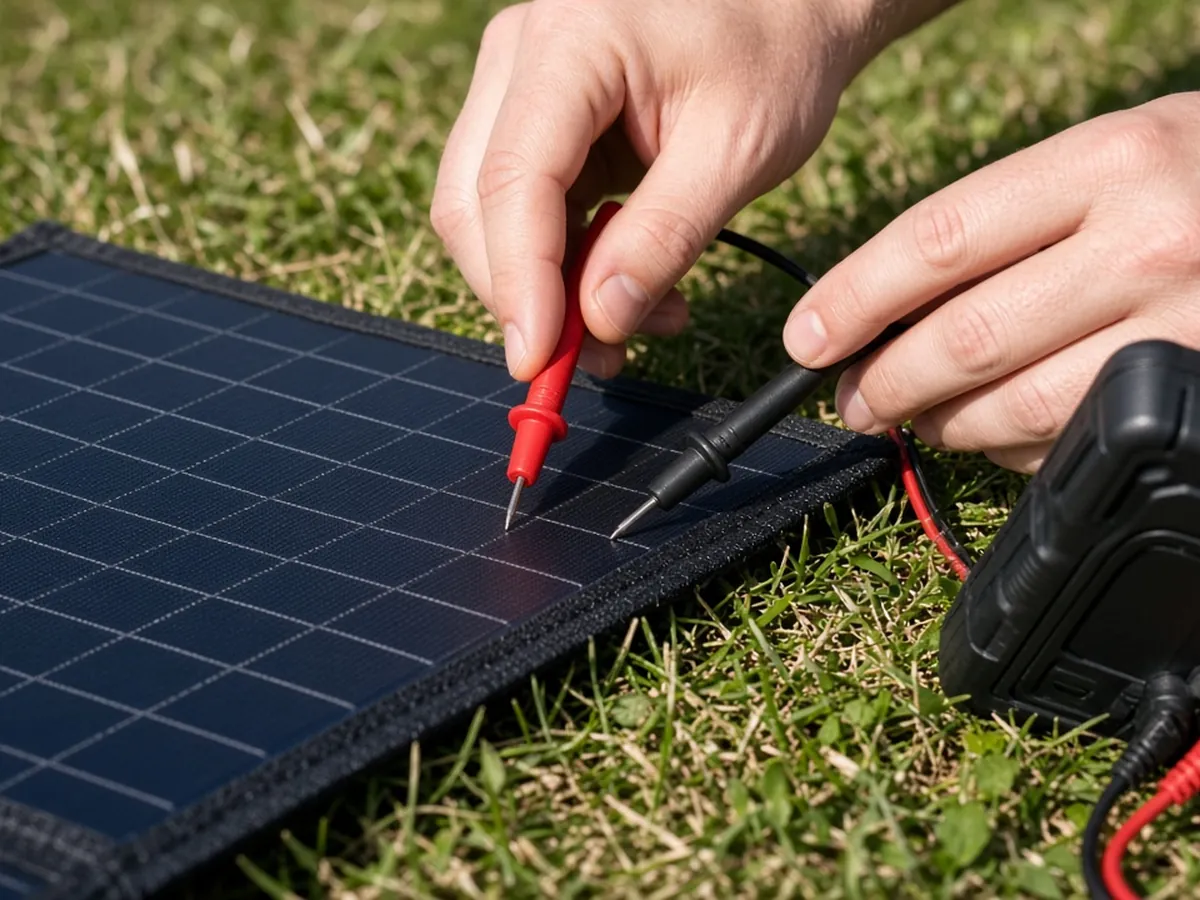
This test checks the panel on its own, with nothing else connected. Pick a clear day, face the panel at the sun, and make sure no part of it is shaded. PVEducation notes that even shading part of one corner of a module causes a dramatic loss in output.
Step 1: Read the panel label
Find the rated Voc (open circuit voltage) and Isc (short circuit current) on the label or spec sheet. Write them down. These are the numbers you compare against. Ratings are given at a standard cell temperature of 25 °C, which a panel in the sun is usually hotter than.
Step 2: Measure open circuit voltage (Voc)
- Disconnect the panel from the power station and any controller.
- Plug the black lead into COM and the red lead into the V socket.
- Set the meter to DC volts, on a range higher than the rated Voc. PVEducation suggests the 200 V setting if you’re unsure.
- Touch red to the positive lead and black to the negative lead. On MC4 plugs, touch the metal contact inside each connector without letting the probes bridge the two.
- Record the reading, the time and, if you can, the panel’s surface temperature. A negative reading only means the probes are swapped.
Step 3: Measure short circuit current (Isc), only if your meter is rated for it
- Disconnect the meter from the panel before changing settings.
- Move the red lead to the meter’s high-current socket (often labeled 10A) and set it to DC amps. PVEducation’s instructions use the 10 A setting and stress moving the lead so you don’t blow the meter’s fuse.
- Confirm the panel’s rated Isc is below the meter’s current rating. If it isn’t, skip this step.
- Connect the probes to the panel leads briefly, read the value, and disconnect.
- Move the red lead back to the V socket afterwards so the next voltage test doesn’t short the meter.
Some installers avoid measuring Isc through a general-purpose meter at all, because a wrong socket or range can damage the meter or cause an arc. If you’re not comfortable with it, the Voc test plus the power station’s own input reading is still a useful check.
Step 4: Compare and interpret
Multiplying Voc by Isc gives a rough upper figure, not real power. PVEducation’s worked example measured 35.8 V and 10.07 A and, using a typical fill factor of about 0.7, estimated roughly 254 W. The same source cautions that a no-load Voc reading is accurate to within about 10%, while an Isc reading can be off by 50% or more. Treat the test as a “working or not” check, not a performance rating.
Solar panel open circuit voltage: expected vs measured values
Your measured numbers will rarely match the label exactly. What matters is whether the gap makes sense for the conditions.
| Condition | Effect on Voc | Effect on Isc | What it means for the test |
|---|---|---|---|
| Hot panel in summer sun | Lower (silicon cells lose about 2.2 mV per cell per °C above 25 °C) | Rises very slightly (about 0.06% per °C) | Voc several volts under the label on a hot day can be normal |
| Cold, bright day | Higher than the label | Close to normal | Check that the cold Voc still fits under the station’s maximum input voltage |
| Weaker sun (morning, evening, haze) | Drops only a little | Drops roughly in proportion to sunlight | Good Voc with low Isc points to light, not a fault |
| Cloudy day | Still present | Large drop; PVEducation cites about 10–20% of rated output | Don’t judge a panel on a cloudy-day reading |
| Partial shade | May look normal | Can fall sharply | Remove all shade, then retest |
| Near-zero Voc in full sun | — | — | Open circuit: broken cable, failed connector, or internal panel fault |
Temperature correction. For silicon modules, PVEducation gives a simple correction back to 25 °C: corrected Voc = measured Voc + 0.0022 × number of cells × (panel temperature in °C − 25). It also notes cells with higher voltage are somewhat less sensitive to temperature, so treat the result as an estimate.
Why shade hurts so much. Cells in a panel are wired in series, so a shaded cell limits the current of the whole group. Bypass diodes let current route around a shaded group to limit damage and losses, but output from that group is still lost.
Solar panel not charging battery: MC4 connectors and cables
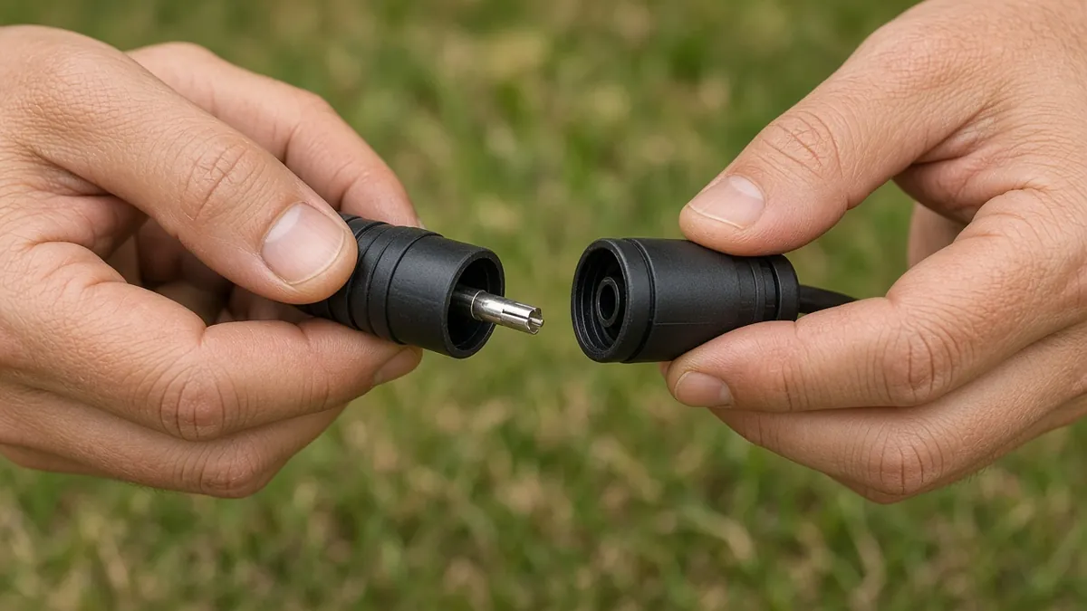
Most “dead panel” reports turn out to be a connection. With the panel disconnected:
- Look inside each MC4 plug. Dirt, water, corrosion or a bent or pushed-back pin all add resistance or break the circuit.
- Check that each pair clicks and locks. A connector that looks joined but isn’t latched can make intermittent contact, which shows up as input that jumps up and down.
- Wiggle-test while watching the input. If the reading changes when you move one connector or cable, you’ve found the fault.
- Check the adapter direction and polarity. MC4-to-station adapters must match the station’s input, and reversed polarity can mean zero input or an error.
- Use the correct port. Make sure the cable goes into the solar or DC input, not a car or USB output.
- Inspect cable runs. Look for cuts, crushed sections, melted insulation and extension cables that are long or thin for the current.
- Measure at the far end. If Voc is fine at the panel but not at the end of the extension cable, the cable or a joint is the problem.
Don’t force connectors that don’t fit, and don’t mix connector types unless the maker says they’re compatible.
Power station input limits: voltage window, MPPT and overvoltage
Even a healthy panel will show zero input if it falls outside what the power station accepts. Check these in the manual for your exact model:
- Voltage window. Solar inputs list a minimum and maximum voltage. Below the minimum the charger may not start, so a single small panel in weak light can read zero even though it works. Above the maximum the station protects itself.
- Overvoltage lockout. If an array’s Voc is above the input limit, the station may refuse to charge or show an error. Because Voc rises in cold weather, an array that works on a warm afternoon can trip the limit on a cold, bright morning. Check the cold-weather Voc against the limit, not just the label value.
- Current and power limits. Inputs also cap current and wattage. Extra panels beyond the cap don’t add charging speed, and some stations simply clamp the input.
- MPPT behavior. A station’s MPPT charger hunts for the panel’s best operating point, so input can wander for a short time after you plug in or when clouds pass. Give it a minute before deciding something’s wrong.
- Battery state and temperature. Charging often slows as the battery approaches full, and many stations limit or pause charging when the battery is too hot or too cold.
- Settings. Some models have charge limits, input modes or app settings that can lower or turn off solar charging.
If the panel tests close to its label in good sun, connections are clean, the array is inside the voltage and current limits and the station still shows nothing, contact the manufacturer with your models and measurements.
For the full setup steps, see how to charge a portable power station with solar panels.
Series and parallel wiring mistakes
Series wiring adds voltage; parallel wiring adds current. Most wiring faults come from forgetting one of those.
- Too much voltage in series. Two or three panels in series can easily exceed a station’s maximum input voltage. Add up the Voc values (and allow for cold weather) before connecting.
- Too much current in parallel. Parallel panels add their currents and can go over the input’s current limit, so the station clamps the input or shows a warning.
- Mismatched panels. In series, the weakest or most shaded panel limits the current of the string. In parallel, panels with different voltages work against each other. Mixing panel models gives unpredictable input.
- A missing link. In a series string, one open connector stops the whole string. In parallel, the array still works but at reduced output, which hides the fault.
- Wrong branch connectors. Parallel Y-branch connectors must be paired positive-to-positive and negative-to-negative.
Test each panel’s Voc on its own, then test the combined array’s Voc at the plug that goes into the station. Series Voc should be roughly the sum of the panels; parallel Voc should be roughly the same as one panel. If not, a connection in the array is wrong. More detail is in solar panels in series or parallel.
Low input that isn’t a fault
Plenty of “underperforming” panels are working normally:
- The panel’s watt rating is measured under standard test conditions, which you rarely get outdoors.
- Heat lowers voltage and power. PVEducation gives roughly a 0.4–0.5% power loss per °C for silicon.
- A panel lying flat or aimed away from the sun collects much less. Check your panel angle and direction.
- Glass behind a window, dust and early or late sun all reduce input.
When to stop and contact the manufacturer
Stop if a connector, cable or the station gets hot, a panel is cracked or delaminating, the same fault code keeps coming back, or the manual calls for service. Don’t open the station, bypass a fuse or leave a test setup unattended. Send the maker your models, the measured Voc and Isc, panel temperature, sky conditions and the exact error shown.
FAQ
How do I test a solar panel with a multimeter?
Disconnect the panel, put it in full unshaded sun, set the meter to DC volts on a range above the panel’s rated Voc, and touch red to positive and black to negative. Compare the reading with the label. For current, disconnect, move the red lead to the high-current socket, set DC amps, and measure briefly, but only if the meter’s current rating is above the panel’s Isc.
Why is my solar panel not charging my battery or power station?
Common causes are shade or weak light, a loose or dirty MC4 connector, the wrong port, reversed adapter polarity, a panel voltage outside the station’s input window, an overvoltage error from too many panels in series, a full or too-hot battery, or a charge setting. Check them in that order.
What should the open circuit voltage of a solar panel be?
Close to the Voc printed on its label. In hot sun it’s normally somewhat lower, and in cold sun somewhat higher. A reading near zero in full sun points to a broken connection or internal fault.
What is short circuit current on a solar panel?
Isc is the current the panel produces when its leads are connected directly with no load. It rises and falls roughly in proportion to sunlight, so a low Isc with normal Voc usually means weak light or shade.
Why does my solar panel show voltage but no current?
Voltage builds up even in weak light, while current needs strong light. If Voc is normal but there’s no current, the light may be poor, the panel may be shaded, or there’s a high-resistance connection. If the station shows zero while the panel itself tests fine, check the cable, adapter and the station’s input limits.
Can cold weather stop solar charging?
Indirectly, yes. Cold raises panel voltage, which can push a series array over the station’s maximum input voltage and trigger overvoltage protection. Many stations also limit charging when the battery is too cold.
Can I use any panel if the connector fits?
No. A matching plug doesn’t mean the panel’s voltage and current fit the station’s input. Check both specifications and the approved configurations in the manual.
Sources
- PVEducation: Module Measurement without Load — Voc/Isc test steps, meter settings, temperature correction, accuracy limits, cloudy-day output.
- PVEducation: Effect of Temperature — Voc, Isc and power temperature behavior of silicon cells.
- PVEducation: Bypass Diodes — how shading affects series-connected cells.
- Your power station’s and panel’s user manuals — input voltage, current, connector and temperature limits for your exact models.